Blog Layout
What are the Differences Between RTDs and NTC Thermistors?
Brian Smith • Sep 22, 2021

Even though they mostly remain unseen, sensors are necessary for every day, essential systems and devices. Temperature is an important measurement of environmental and physical conditions because it is important for many applications. Measuring temperature might seem unimportant for many, but precise and consistent temperature measurement is essential for electronic systems and devices. To deal with issues associated with heat, engineers and designers have several options at their disposal. On the surface, selecting the best sensors for a device and application can feel overwhelming. Although there are many options, two are ideal for most situations: NTC and RTD.
NTC Thermistors
– NTC stands for negative temperature coefficient, and they are thermally sensitive resistors. They demonstrate a negative temperature coefficient of resistance, which is done through a decrease in resistance proportionate to temperature increase. This is referred to as a non-linear relationship between temperature and resistance. This is most beneficial in an application that demands accurate temperature measurements. NTC thermistors
work within a narrow range of temperatures.
RTDs
– RTDs stand for resistance temperature detectors, and they are also thermally sensitive resistors (like NTC thermistors). The difference, however, is that an RTD exhibits a positive temperature coefficient, whereas an NTC thermistor does the opposite. An RTD increases the resistance of a device as the temperature increases. An NTC is considered non-linear, and RTD is nearly linear (for a wide range of temperatures). Many engineers find the linear response beneficial when converting resistance readings into clear and accurate temperature values. As a result of this function, RTDs is often the more suitable option for applications with a wide range of operating temperatures.
General
RTD stands for resistance temperature detector, and it is a type of temperature sensor . These sensors change resistance as temperature changes. The resistance increases when the temperature of the sensor increases. The sensor works on a resistance versus temperature relationship. It is essential to keep in mind that these are passive sensors and do not produce an output of their own. To compensate for this issue, an external electronic device is used to measure the sensor's resistance. This is done by passing small electrical currents through the sensor to generate a voltage. RTD sensors come in three main configurations: · 2-Wire · 3-Wire · 4-Wire A 2-wire RTD uses a single wire to connect both ends of the RTD element. This construction is the most simplistic form of an RTD. All resistance calculations include circuit elements, meaning that there is a higher degree of error due to the wire resistance. Two-wire RTDs are best in applications that require short wires and high resistance sensors. Most importantly, high accuracy should not be the essential factor. A common wire construction is a 3-wire construction. One side of the element has one wire connected, and the other side has two wires attached. Adding these extra connections allows the device to reduce the extra resistance created within the circuit due to the wires. A 3 wire RTD, unlike the two-wire variant, may give a more accurate reading. A 4-wire RTD is more complex compared to the two other types. You can often find these RTD's used in laboratory applications that require the highest possible levels of accuracy. This type of RTD assembly can quickly compensate for errors created through wire resistance. NTC Thermistors How do Thermistors Work Common Causes of Thermistor Failure Moisture Induced Failure in NTC Thermistors
NTC thermistors are widely regarded as the most common type of thermistor. There are other options for highly sensitive temperature sensing in a small size. What makes an NTC, or negative temperature coefficient, thermistor so highly regarded is its ability to alter its resistance characteristics with designated temperatures, with relatively high sensitivity. A negative temperature coefficient refers to the resistance change based on the temperature change. NTC thermistors operate by decreasing resistance as temperature increases. There are many practical applications for negative temperature coefficients. In many of these cases, an NTC thermistor is not just the smart choice but the best one. Typical applications of a negative temperature coefficient include: · Medical Devices & Healthcare Applications · Industrial Processing · Environmental & Aerospace Monitoring · Telecommunication & High-Speed Computing Equipment · Transportation & Automotive Applications What makes negative temperature coefficient thermistors the right choice for temperature sensing? First and foremost, they may be accurate. NTC thermistors also may have a fast response time and a low cost without sacrificing performance. They are highly appropriate for many applications with small temperature ranges and compatible with a two-wire connection system. Although NTC thermistors are often the right choice, they should not be used for all designs. Being smart and making the right choice for temperature sensing is essential for performance and safety so take the time to make the proper considerations. Related Reading Common Questions About NTC Thermistors How do Thermistors Work Understanding Bead Type Thermistors
Many of the electronic devices we use daily contain some form of the temperature sensor. From devices designed to get hot and cold (freezer/microwave) to personal electronics (computers)...
The Steinhart-Hart equation is a polynomial formula used to calculate an NTC thermistor's temperature versus its resistance relationship.
NTC Thermistor probes are great because their applications are almost endless. The devices measure both liquid and temperature levels within highly complex industries...
Although there are similarities between thermistors, each one has unique differences. In its most basic terms, a thermistor is a semiconductor
NTC thermistors offer engineers various applications while managing to maintain high levels of stability and accuracy. Thermistors are efficient and cost-effective without cutting corners and sacrificing performance. The three most common applications of an NTC thermistor are control, measurements, and compensation. Although thermistors are used for various applications, they are most often used as resistance thermometers because they are accurate and versatile. Thermistor probes are also ideal for an application that functions in low ranger temperatures. Thermistors are also employed throughout the transportation and automotive industry. In modern cars, you are likely to find upwards of 50 separate thermistor devices. Thermistors are used for HVAC functions and vital applications like emissions control and process controls. The thermistor can also be found functioning in monitoring and maintaining engine temperature. The military uses thermistors within military vehicles, including trucks and tanks. NTC thermistors also improve the safety of devices they function within. For instance, the devices are used for hot glue, plastic laminating, and fire safety. Industrial soldering iron, which reaches dangerously high temperatures, relies on thermistors to maintain accurate and consistent temperatures. Thermistors are also used for: Chemical Analysis Equipment Copy Machines Telecommunications Photographic processing Solar Panels Oceanographic research equipment Household/Consumer Products Scientific Instrumentation Medical Equipment The potential application and instrumentation of NTC thermistor probes seem to be almost endless. From winding compensation to gain stabilization, there is almost nothing these devices cannot accomplish. To find out more information about designing and using thermistors, you should give us a call today!
Thermistors offer many benefits, which is why they are widely used in many applications and industries. Thermistors are all around us, from life-saving medical equipment to HVAC systems that keep us comfortable. Although these devices are affordable, powerful, and reliable, they suffer from certain limitations, which means they are not ideal for all applications. To calculate thermistor-resistance measurements, an individual needs a voltage measurement. The resolution of a voltmeter limits the accuracy of readings. It is also important to keep in mind that input bias currents and input-offset voltage of operation amplifiers also directly affect accuracy. To properly measure resistance, all currents need to pass through a thermistor that dissipates heat. This results in a small temperature increase, which is labels as self-heating errors. This type of error functions in proportion to the dissipated power plus the thermal resistance of thermistors and the environment they function within. Internal thermal resistance changes depending upon the material and dimensions of the thermistor, whereas external thermal resistance depends on the thermal conductivity level of the medium that surrounds the thermistor. In many applications, self-heating is considered a serious problem for measurements that are made over an extensive temperature range. Stray thermal influences affect the performance of thermistors . Because of the high thermal resistance that is found between the environment and thermistor, the devices are prone to stray thermal influences. The two main culprits are the heat that is conducted along lead wires and infrared radiation. The problem is often made worse when there is a poor thermal design. The problem is most often experienced when measuring surface temperature or air.
Within a controlled system, thermistors have a specific function. A temperature controller is used to monitor the temperature of thermistors that then instruct a heater or cooler to turn on and off. The goal is to maintain a consistent temperature within the thermistor and the target device. Some of the most commonly controlled systems that use thermistors include air conditioning units and refrigerators (to name a few). Sensors have small amounts of currents, called bias currents, running through them. The current is supplied from the temperature controller. Controllers do not read resistance, which means that it must be converted into voltage changes. This is done with the help of a current source that applies a bias current across the entire thermistor, hence producing controlled voltage. Thermistor A thermistor needs to be placed close to the device, requiring control to guarantee the highest levels of accuracy. This can be done by attaching or embedding the thermistor. As the thermistor moves further away from the device, users experience greater thermal lag time that negatively affects the accuracy of temperature measurements. Avoid placing thermistors away from thermoelectric coolers because that also reduces stability. Keeping thermistors close to devices ensures a quick reaction time to temperature changes. This is a key aspect of maintaining consistent temperatures within controlled systems. Placement of a thermistor within a controlled system is the first consideration to make, and once that is finished, individuals can begin to determine base thermistor resistance, setpoint, and bias current. Related Reading When is it Necessary to Use NTC Thermistors? What is the Difference Between Thermistors and Thermocouples Moisture Induced Failure in NTC Thermistors
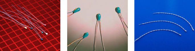
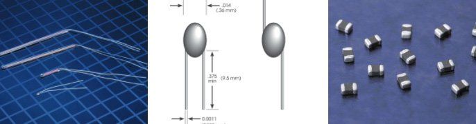
Epoxy is often used to create a protective barrier for NTC thermistors , howver epoxy is not a waterproof seal. Engineers may use epoxy-protected thermistors to protect thermal conductivity and high dielectric strength. These thermistors are tear-drop-shaped bead that has two radial wire leads. These thermistors are used in medical devices that measure air temperature and airflow. You may also find epoxy bead thermistors in automotive applications. NTC thermistors Protecting NTC thermistors from direct exposure to fluids is critical for the function of different devices. Thermally conductive epoxy can be used within a stainless-steel housing, but is not fully waterproof. Glass parts or laser welded parts that are hermetically sealed would be more ideal for moisture environments. Related Reading How do Thermistors Work Thermistor and Fire Alarms Differences Between Glass Probe and Glass Bead Thermistors
Technical
Thermistors are used as a resistor that is affected by temperature/resistance thermometer. Precise monitoring and responses to temperature change are the jobs of a thermistor.
Thermistors are a type of semiconductor. What differentiates a thermistor from other semiconductors is the device’s ability to operate in significantly lower resistances.
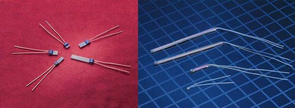
Thermistors are constructed from metal oxide semiconductors, and they are formed into different shapes (disk, bead, cylinder). thermistors are also encapsulated in materials like glass or epoxy.
Thermistors are used because of their ability to measure temperature. NTC thermistors having a highly nonlinear change in resistance and reducing resistance as temperature increases.
When it comes to measuring liquid levels and temperatures, NTC thermistor probes are one of your best options. Thermistors offer high sensitivity, interchangeability, so they are often used in the medical field.
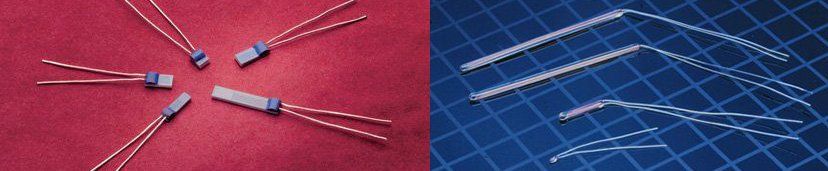
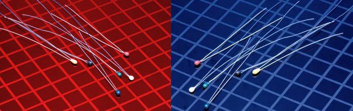
Bead type thermistors are often fabricated by applying a slurry of mixed metal oxides with a binder onto two spaced platinum alloy lead wires.
NTC Thermistors are commonly used in a wide range of applications and devices. Thermistors are the most common devices used for temperature measurement.
Taking care of a thermistor is important to ensure that they run correctly. When a thermistor malfunctions and gives inaccurate readings, it can have detrimental performance results.
Thermistors are found in hairdryers, refrigerators, and vehicles, so they must function properly. They are used as temperature sensors, and they are also extremely beneficial for protecting currents.
Design tricks are used to minimize potential failures caused by moisture, The most effective solution is to use glass-encapsulated thermistors.
Comparisons
Glass probe thermistors are best suited in applications that require high stability and ruggedness. Our team of engineers can help you narrow down your choices.
Both thermistors and thermocouples are viable options for temperature measurement and control. Both resistance sensors serve the same function but work differently.
NTC thermistors are made up of sintered metal oxides. Some of the metals found in an NTC thermistor are iron, nickel, manganese, aluminum, copper, and cobalt.
Thermistor accuracy is the best around. They are one of the most accurate types of temperature sensors. However the level of accuracy will depend on the type of thermistor you get.
You can add heat to a thermistor by moving a heated soldering iron up to the tip. This will allow an individual to see whether they are using NTC or PTC thermistors.
When acquiring Thermistors, RTDs, or Thermocouples, you should contact a professional in the industry who can help you choose the best possible device.
Thermistors are created from a combination of metal oxides. Most industries choose to use RTDs and thermistors, which convert temperature into electrical signals.
Applications
Thermistors function as both a thermo-sensitive device and a heating element. They play an active role in many different applications.
Thermistor and NTC Thermistor sensors are broken into the distinct categories, Sensors are placed relevant to their electrical characteristics that are exploited in the application.
NTC thermistors can be defined as non-linear resistors that change resistance characteristics based on temperature. do not hesitate to reach out to our gifted team.
Glass encapsulated thermistors are hermetically sealed to eliminate resistance reading flaws that are caused by moisture penetrating the thermistor.
Over the past 34 years, Sensor Scientific has supplied tens of millions of low cost, high reliability NTC (negative temperature coefficient) thermistors for biomedical applications.
A thermistor’s ability to detect temperature makes it a crucial tool for many different industries. One of the most important uses of a thermistor is to create fire alarms that go off when there are sudden and drastic changes to temperature in a given room/area.
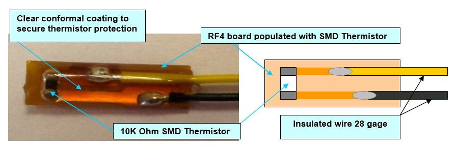
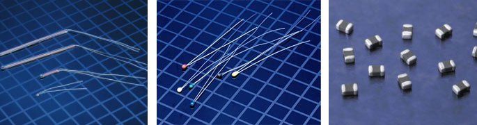
Sensor Scientific manufacturers NTC thermistors. We developed a surface mount NTC miniature assembly for use in any industry where battery temperature should be monitored.
The size of thermistors also makes them practical for use in small electronics. Thermistors come in different shapes and sizes, so it is important to pick thermistors that work best for your desired application.
There are multiple options when it comes to temperature sensing solutions, Two of the most common options on the market are thermistors and analog temperature sensors.
Have you ever seen a cell phone screen that warns the user of overheating, or have you felt how hot a laptop computer can get? As electronic technologies get smaller and more compact, temperature becomes more difficult to manage. As a result of many devices function within a larger unit, high levels of heat are generated. If the heat within the devices is not compensated for, there is an incredibly high likelihood of malfunction or breakage. Thermistors are widely used in the electronics industry, and perform actions like turning on or off fans depending on ambient temperature. Although the main function of a thermistor is to monitoring temperature, it can be used for inrush surge current suppression. It also has the ability to make power factor corrections. The devices are better suited for application in smaller devices. As the devices get larger, a solenoid becomes more practical. Thermistors Thermistors allow for high power efficiency and temperature compensation when properly used in small electronic devices. Utilizing the proper thermistors allows for technology to work as well and seamlessly as it does. For more information about acquiring and using thermistors, call Sensor SCI today for more information. Related Reading Temperature Sensor Assemblies We offer a wide range of temperature sensing probes (thermistors, RTD, glass probe thermistor) that are employed in a variety of industries that require temperature sensing applications. Thermistors and Battery Safety Glossary of Important NTC Thermistor Terms
RTD
There are limitations for RTDs (resistance temperature detectors), so knowing the difference between each type is an essential part of proper engineering and functionality. The most common RTDs include 2-wire, 3-wire, 4-wire sensors. To pick the proper sensor for your application, you need to know the basic differences. Two-Wire RTDs are the most simplistic versions because they are only a wire resistor. These resistors only have two leads, which means that resistance increases as temperature goes up. The highest quality RTDs are constructed with platinum wires because they offer linear and predictable resistance. When platinum is applied to two copper wire leads, the resistance of the wire goes up drastically. The longer the wire lead, the more resistance the wire has. Three-Wire RTDs are a great option for avoiding lead wire resistance. The three-wire variant is often seen as the most commonly used configuration because they are robust and accurate. The three wires contain a single lead attached to a terminal, and the other two wires are connected to the terminal of the RTD. For the sake of consistent performance, all wires are constructed from the same material, are the same length, and have an approximately equal resistance throughout. Four-Wire RTDs have a similar principle as a three-wire variant. The main difference between these two RTDS is that a four-wire version has two wires attached to both terminals. Although they are typically more expensive than the two versions listed above, they are the most accurate RTD. Related Reading When to Use a PT 100 and PT 1000 Thermistor? Common RTD Wiring Configurations Understanding How RTD Sensors Work
Sensing elements found in RTD’s (resistance temperature detectors) are categorized based on the type of metal used for construction and the device's resistance at set temperatures. Two of the most common categories of RTD sensors are RTD PT 100 and RTD PT 1000 . A PT 100 and 1000 sensors are made with platinum, but PT 1000 sensors have a resistance value of 1000 O at 0 degrees Celsius, and PT 100 sensors have a resistance value of 100 O at 0 degrees Celsius. Both sensor types are available within a similar range of tolerances, and as a result, both can have similarities. Although the two sensors can be compared, when it comes to resistance value reading, PT 1000 thermistors show a reading by a factor of 10 compared to PT 100 sensors at the same temperature. Although the sensors are used interchangeably (depending on the instrument), there are certain instances where a PT 100 sensor is a better and more accurate option. PT 100 sensors are commonly used in both commercial and industrial applications. This type of thermistor is best suited within three and four-wire circuit configurations. A PT 100 sensor has resistance across the sensing element lower than that of a PT 1000 sensor. A PT 100 sensor is sold in wire-round and thin-film constructions. An RTD PT 100 sensor is the most common version because it is suitable for various instrumentation and products. PT 1000 sensors should be used in two-wire circuit configurations because these sensors have greater resistance. These sensors are great because their high resistance values can easily be measured with less current. As a result, the power consumption of these devices is lower, and they produce little heat. Related Reading NTC Thermistors and Epoxy Common Thermistor Configurations Three Common Thermistor Questions
RTD assemblies can come in many shapes, sizes, and configurations, and so you should take special care when choosing a RTD assembly for specific applications. Learning about RTD assemblies makes it easier to choose wisely. What is the difference between 2, 3, and 4 wire configurations? PT 100 RTDs contain sensing elements introducing additional resistance to a circuit (through connectors, lead wires, and measuring instruments). As a result, you must remove unwanted resistance during the measuring of voltage drops across the sensing element. The configuration of a circuit determines the accuracy of resistance being calculated and the amount of distortion created from resistance within the circuitry. A sensor's lead wire, used between the measuring instrument and the resistance element, offers resistance that also needs to be acknowledged. Two-Wire Configuration – this type of configuration is considered the simplest RTD circuit design. A single lead wire connects the ends of the RTD element with the monitoring device. When calculating resistance, readings include the resistance coming from lead wires and connectors. Three-Wire Configurations – these are the most used configurations for RTD circuit design. It is seen as an industrial process for monitoring applications. Two wires link a sensing element to a monitoring device. Four-Wire Configuration – this is the most complex of configurations. In this design, two wires link a sensing element to monitoring devices (both sides of the element). One set of wires is used to deliver currents needed for measurements. The other set of wires is responsible for measuring voltage drops over the resistor. Related Reading The Main Reason to Use NTC Thermistors What is Sensor Drift and Self-Heating NTC and PTC Thermistors
RTD stands for resistance temperature detector, and they are often made from a highly pure platinum metal.
PT 100 and Pt 1000 RTD elements are the two most common platinum RTD sensors. PT100 sensors have a nominal resistance of 100Ω at 0°C (ice point).
There are two RTD sensors elements to choose from: knowing a little about each will help ensure you are using the right variation for your specific application.
Of all RTDs on the market, the PT100 sensor is the most popular. It uses platinum, which allows the sensor to have a resistance of 100 ohms at close to 0°C.
When choosing a bias current and thermistor, it is crucial to decide on one where voltage developed in the middle of the range.controller feedback inputs should be in voltage.
When building RTDs and thermistors some practical precautions must be taken. Being mindful of these precautions will help to ensure that your applications work correctly.
Resistive temperature devices, like thermistors and RTDs, are commonly used as sensors to measure temperature. the thermistor method of detecting fire requires heat to be the only force necessary for activation.
Assemblies
A thermistor's primary function is to measure the temperature of devices.You must consider the determining base of thermistor resistance, as well as the current bias of the sensor.
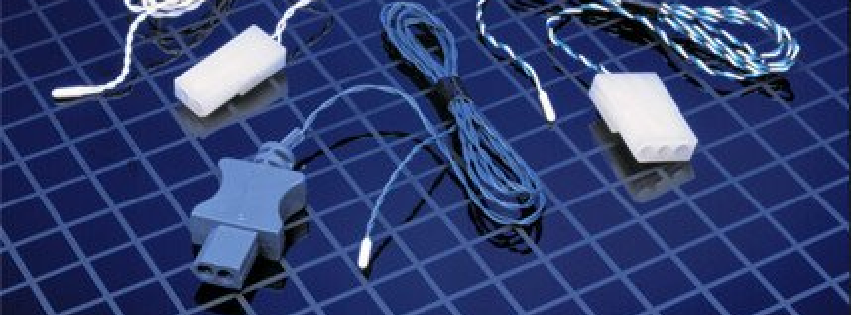
The sensing element (RTD, NTC thermistor, thermocouple, etc.) is a fundamental consideration depending on several factors such as stability, accuracy, temperature range, etc.
We'll Design, Develop & Manufacture to Your Needs.
LET'S WORK TOGETHER!
6 Kings Bridge RoadFairfield, NJ 07004, USA
If you are looking for Thermistor, Standard Chip thermistors, temperature probes for data loggers, Glass Probe Thermistors,
SB Series SMD Chip Thermistor, rtd probe, pt100 rtd,
pt1000 temperature sensor, rtd temperature probe, ntc thermistor, we are your #1 choice.